
Every molded part carries a scar — the vestige left where molten plastic entered the cavity. Most buyers never think about the gate until a blemish lands on a show surface or a degating operation lands on an invoice. But where the plastic enters decides far more than cosmetics: it sets the flow pattern, fixes where weld lines form, determines how well thick sections pack, and controls a meaningful slice of cycle time. Here is how gate type and gate location actually play out — and why the decision belongs in design review, not in the toolroom after steel is cut.
The gate runs the clock
Filling the cavity is the fast part. After fill, the press switches to pack and hold: pressure keeps feeding material through the gate to compensate for the part shrinking as it cools. That only works while the gate is still molten. The moment the gate freezes, packing is over — whatever shrink remains shows up as sink marks, voids, or dimensions drifting small.
Gate freeze time therefore governs the hold phase, and the hold phase is a big block of the cycle. An undersized gate seals early and starves thick sections. An oversized gate stays open long after the part needs it, stretching hold time and cycle for nothing. The widely used way to dial this in is a gate-seal study — increase hold time in steps and weigh parts until the weight stops climbing. That point is gate seal, and holding past it is wasted seconds on every shot for the life of the program.
Gate types and their trade-offs
There is no universally best gate — each type trades vestige quality, degating labor, tooling complexity, and shear into the part differently:
| Gate type | Vestige and cosmetics | Degating | Typical use |
|---|---|---|---|
| Edge gate | Visible vestige on the parting line edge | Manual trim or fixture | Simple, robust default for non-cosmetic edges |
| Fan / tab gate | Wider witness, but low shear and even flow | Manual trim, then tab removal | Flat, cosmetic, or warp-sensitive parts |
| Sub / tunnel gate | Small dot, usually on a B surface | Self-degating at ejection | Automation-friendly, higher-volume parts |
| Cashew gate | Vestige tucked onto hidden or underside features | Self-degating at ejection | Cosmetic parts needing a hidden gate |
| Pin gates (3-plate tool) | Small vestige, allows top-center gating | Self-degating; runner pulled separately | Round or multi-gated parts gated off the parting line |
| Hot tip (hot runner) | Small vestige directly on the part surface | None — no runner at all | High volume; eliminates runner scrap and regrind |
| Valve gate (hot runner) | Cleanest vestige available; pin shuts the gate flush | None | Class-A surfaces; sequential filling of large parts |
Valve gates deserve one extra note: because each gate opens on command, several of them can fire in sequence as the flow front passes — which lets a large part fill like a single-gated part, with no weld line where two fronts would have collided. That trick has rescued more than one large cosmetic panel.
Placement physics: flow, welds, and packing
The gate is where the flow pattern is born, and the flow pattern decides almost everything downstream:
- Weld lines form where flow fronts meet. Plastic splits around every hole, boss, and core, and rejoins on the far side — cooler, weaker, and visible. You cannot eliminate weld lines on a part with holes, but moving the gate moves them: into a low-stress region, off the show surface, away from a snap arm that will see load.
- Gate into the thick section. Plastic should flow from thick to thin, so the thick region stays connected to packing pressure the longest. Gate into a thin wall and the thin section freezes off first, leaving the thick region beyond it unpacked — sink and voids follow. This is the same thick-to-thin logic we covered in our wall-thickness DFM post, seen from the tool side.
- Jetting and gate blush live near the gate. A gate that fires straight into an open cavity produces jetting — a worm-track of snake-like material frozen on the surface. Aiming the gate at a wall or core pin breaks the jet. High shear through a small gate shows up as blush (a hazy halo) and splay near the gate; fan and tab gates exist largely because they spread the flow and drop the shear for cosmetic and flat parts.
Cosmetics: A surface, B surface, and texture
The first cosmetic question on any gating discussion is blunt: which surface can take the vestige? Sub and cashew gates tuck it onto the B side. A 3-plate tool with pin gates can drop a small vestige dead-center on top of a round part — often hidden in a recess. Hot tips leave their mark right on the surface, so on a show face that mark needs a plan: a textured area, a label zone, a logo pad.
Texture changes the math. A heavy texture hides gate blush, minor flow marks, and faint weld lines that a high-gloss finish would advertise. Gloss surfaces are unforgiving — they show shear marks near the gate and telegraph every flow hesitation. If the part is glossy and the surface is class-A, the conversation usually ends at a valve gate, placed where a moldflow study says the fill stays balanced.
Degating: labor you choose at the tool design stage
Every cold-runner gate must be separated from the part, and how that happens is decided when the tool is designed, not when the parts are quoted. Edge, fan, and tab gates need an operator or a fixture — seconds of labor per part, every part, plus the variation that hand-trimming brings to the vestige. Sub and tunnel gates shear off as the part ejects, which is why automated cells love them: the robot picks parts, the runner drops, nobody touches a clipper. Hot runners remove the question entirely — no runner, no regrind stream, no degating. The hot runner system costs more up front; on high-volume programs the material and labor savings usually buy it back, and a quote should show that math rather than hide it.
Answer it in software, before steel
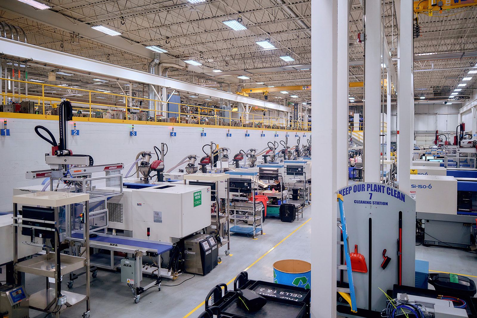
Twenty years ago, gate location was experience plus a tryout — and a wrong guess meant welding and re-cutting steel. Today the question gets answered before the tool is built. Moldflow simulation is standard on every new tooling program at Wise: we model candidate gate locations, watch where the weld lines land, check that thick sections stay packed, and predict gate freeze before anyone cuts a pocket. Our engineering team runs that analysis as part of design review, and on the floor, RJG-instrumented scientific molding verifies the same gate-seal behavior in the actual process — so the cycle time you were quoted is the cycle time you get.
Bring the gate conversation forward
Gate type and gate location are one-time decisions with a per-part price tag attached for the life of the program — in cycle time, in degating labor, in cosmetic yield. The cheapest moment to get them right is while the design is still soft. If you have a part where the show surface and the gating fight each other, or a quote where degating labor looks suspicious, send it over — we will run the flow analysis and show you the options before anyone cuts steel.